Turning CAD Models into 3D Printed Parts
How to evaluate build direction, support structures, radii placement and wall thickness to optimise you design for 3D Printing

Because 3D-printed parts are built up layer by layer, designing CAD files for 3D printing can present unique challenges for engineers. Even the laws of gravity play a part. The following design considerations are critical to follow across all CAD software applications. Continue reading to learn more.
The Effect of Build Direction on 3D Printing
If you are designing or optimising a part for 3D printing, the first decision to make is the intended build direction. While shorter heights typically translate into shorter build times and lower cost, in the end, accuracy and strength are usually more important.
In general, it is better to have the more detailed side of the part facing up during the print process. Cylindrical features are most accurate with the cylindrical cross-section in the draw plane. Generally, the goals of optimisation is to reduce the need for support material, and to reduce the impact of material shrink that occurs from drastic changes in cross-section. You can explore this in more detail, in our article on key considerations for 3D printed part orientation. .


The 45 Degree Rule
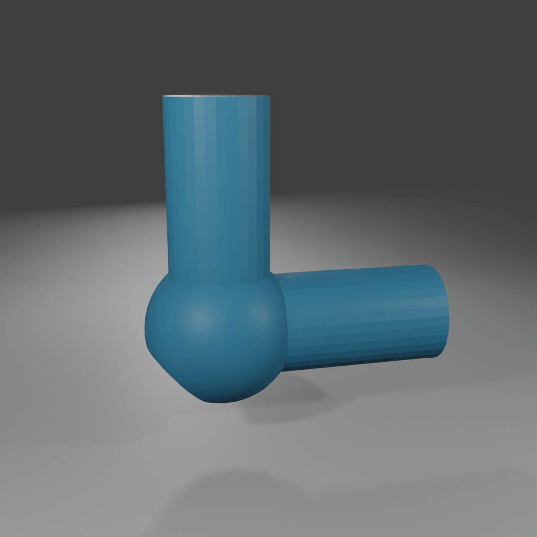
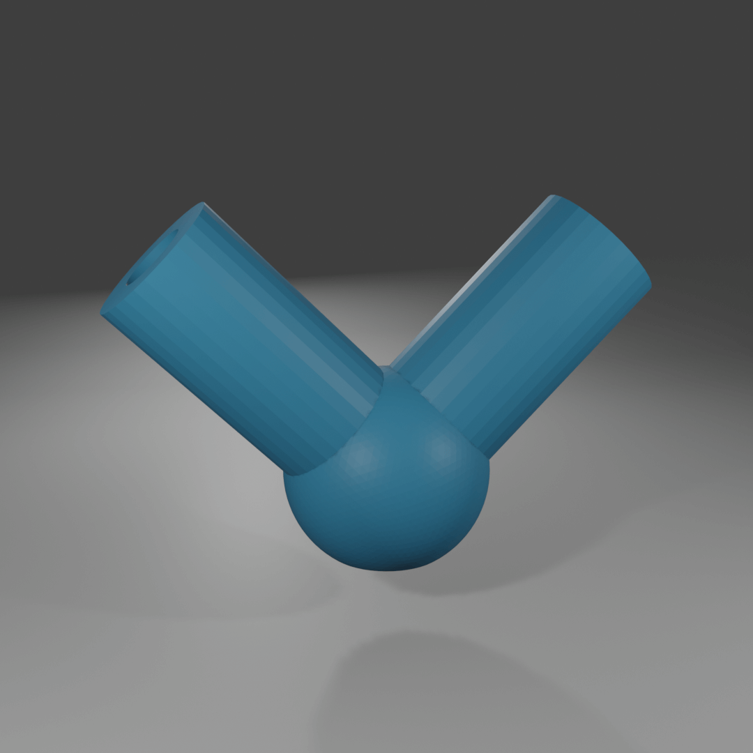
For most additive technologies that require supports, surfaces 45 degrees and steeper are self-supporting. Eliminating unnecessary supports is a great way to mitigate costs, as any supports that are added also add to material cost, print time, and labour to remove. Some specific materials and processes may require 55 degrees or steeper to be self-supporting, while SLS and MJF do not require supports at all. For those two, this rule does not apply.
Add Radii to 3D Printed Parts
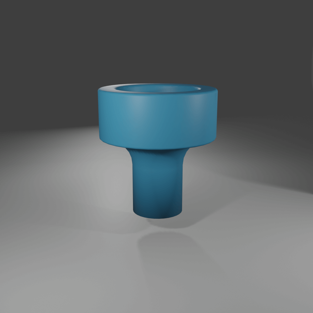
One of the easiest ways to improve accuracy and strength of 3D-printed parts is to add radii to all internal and external hard corners that the design allows. This can mitigate the material shrink that happens layer-by-layer, making the parts more accurate with less surface defects. It also spreads out stress that accumulates in interior corners and makes the parts stronger and less likely to crack under load.
For some materials and printing processes (like titanium printed via DMLS), radii are required to keep the parts from cracking during the printing process due to material shrink. Even a radius as small as 0.5mm can be enough to mitigate this risk.


Uniform Wall Thickness
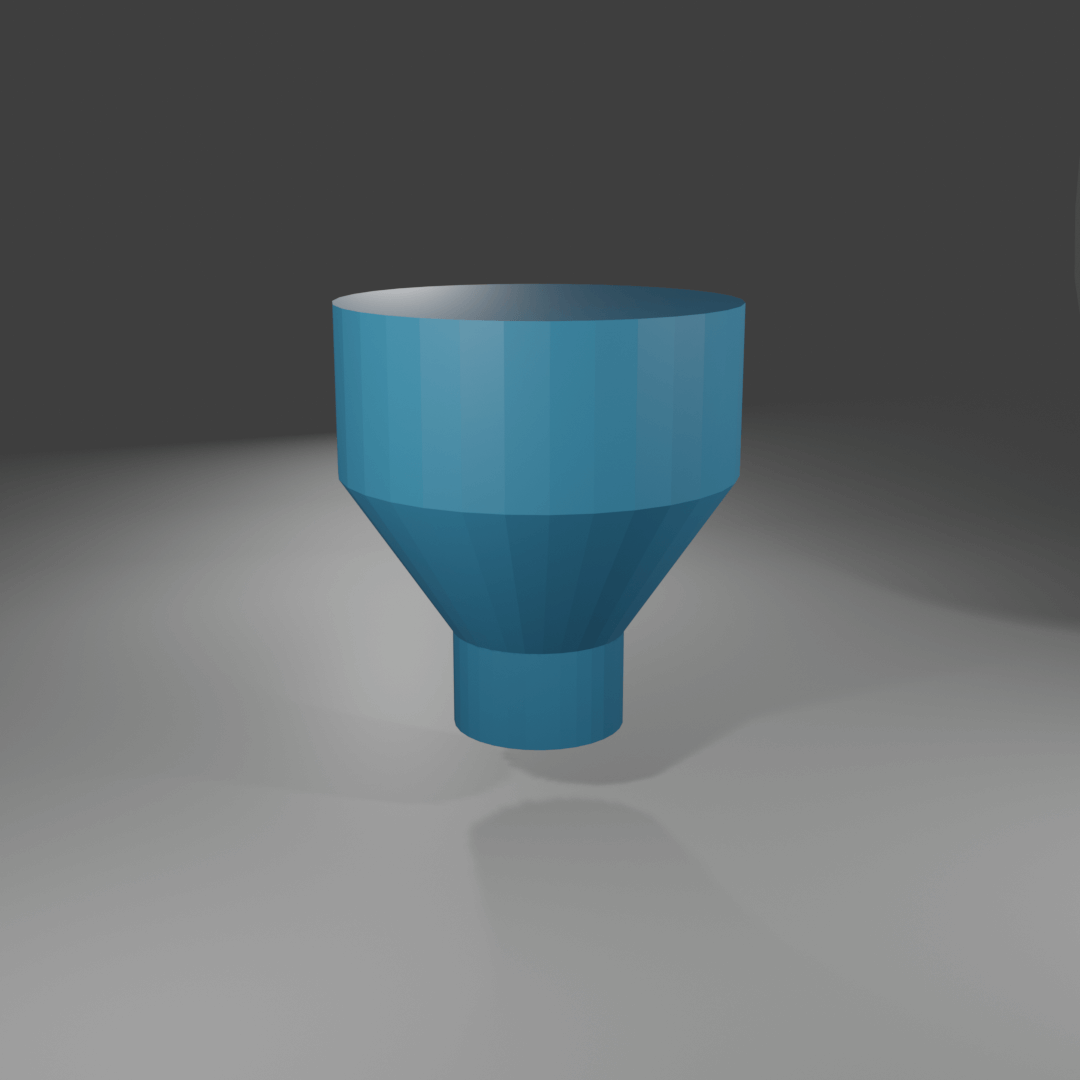
Many printing technologies are susceptible to material shrink, which can affect tolerances and aesthetics. This is most noticeable when the parts undergo drastic changes in cross-section during the print. It is best to core out thick areas and leave the cavity accessible to the environment so that the supports or excess material can be removed after the print.
If printing in FDM, this rule can often be ignored. The partial infill of FDM allows parts to have a relatively uniform wall thickness, even if the CAD model itself undergoes large thickness transitions.
Still have questions about the best way to handle your design? Reach out to us by phone +44 (0) 1952 683047 or email [email protected].


