Draft – Improving Part Mouldability
Your masterclass in product design and development
Protolabs’ Insight video series
Our Insight video series will help you master digital manufacturing.
Every Friday we’ll post a new video – each one giving you a deeper Insight into how to design better parts. We’ll cover specific topics such as choosing the right 3D printing material, optimising your design for CNC machining, surface finishes for moulded parts, and much more besides.
So join us and don’t miss out.
Insight: Draft – improving Part Mouldability
Hi and welcome to this week’s Insight video for Friday.
I hope you’ve been having a great week so far, and that I can help round it off with the next video in our series of tips and tricks for digital manufacturing. We’re hoping these short videos will help to clear up some myths, get folks talking about the technology and save you some time and some money.
This time around we’re going to be taking a look at a good draft, and we’re not just talking about a solid plan or a type of beer either.

No, in the world of plastic injection moulding a draft is essentially a taper applied to the faces of the parts. It’s a vital part of the design, because if you ignore a draft entirely your parts run the risk of poor cosmetic finishes, warping thanks to moulding stresses and a chance that they may not eject smoothly from the mould.
A bad time all round, really.
With that in mind, here are a few tips for making your draft work the way it’s meant to.

First up, draft early. It’s really easy to ignore putting your draft in through the early stages when you’re prototyping with 3D printed or CNC machined parts, because those processes don’t need one. But if you are planning on eventually moving your design over to injection moulding, you can suddenly run into a wall. You realise that you need to put a draft in, but your design was meant to be finished. So, back to prototyping…
Nightmare.
From the start of your process to final production, make sure you’re always designing for your future needs, not just your current ones. Don’t print, or machine, yourself into a corner by investing time and money into a design that just won’t work when it comes to be moulded.
Another thing you need to be remembering throughout the design process is the surface finish you’re looking for.
The reason for this is that a highly textured surface can end up locking the part into place in the mould. Having a draft can help prevent this. It allows the part to move without the texture catching on the mould surface – but the more heavily textured a part’s finish is, the greater the draft needs to be.
And this is just one of the many factors you need to bear in mind when deciding on what draft you need. This decision can be a little tricky sometimes, as there’s no single draft angle that’ll work for every kind of geometry, material, wall thickness and all those other factors. Fortunately, there are some simple rules – well, more guidelines – that you can follow to keep your draft on point.
The most important of these is that when designing a part, you should apply as much draft angle as possible. A rough rule of thumb is one degree of draft per one inch of cavity depth, but this can shift about according to all those factors I just mentioned.

If you have a shutoff or a light textured finish you’re looking at a minimum of about three degrees, and if you have a heavy texture it’s more like five.
On parts where a draft may negatively impact the performance – where you need a vertical face, for example, it’s still best to include at least something. Even as little as half or a quarter of a degree can have a marked performance over having zero. If you do hit a situation like this, though, the best thing to do is just have a talk with the manufacturer before you finalise anything. They should be able to give advice based on materials, textures, etc.
Another area that can be tricky to add draft to is enclosures. If you don’t apply it correctly, you can end up creating deep ribs in the mould that make everything from ejection to finishing much more difficult that it needs to be.
Instead of doing that, consider taking a core-cavity approach to your design. This opens up the mould cavity and core for polishing, accelerates manufacturing speed and, in general, brings added ease during the moulding process.
Adding draft to an enclosure can create issues if it isn’t applied correctly. When applying draft to the inside and outside walls, design these walls parallel to each other to avoid deep ribs in the mould that make venting, ejection, mould finishing, and manufacturing more difficult. Consider a core-cavity approach to design as this opens up the mould cavity and core for polishing, accelerates manufacturing speed and, in general, brings added ease during the moulding process.
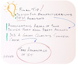
The final tip I have today is one of the easiest to take advantage of, because it’s normally free. Your supplier should offer a free design for manufacturability (DFM) analysis on 3D CAD models. It should give you a whole heap of information, which includes highlighting areas of your design that need draft angles.

It’s just a good quality control check, and I encourage everybody to take advantage of it.
Until next week.
With special thanks to Natalie Constable.


