Manufacturing Analysis
Before you approve your part for manufacturing, it’s helpful to get instant feedback that lets you know it’s ready for our systems. Our advanced design for manufacturing (DFM) analysis gives you peace of mind before you hit the approve button.
Manufacturing Analysis
- You’ll receive an email once your quote is ready with a 3D analysis of your design
- Once you sign in you’ll find feedback on the geometry of your CAD file to improve part manufacturability
- Improvements to the revision based on the analysis process drastically accelerate the design feedback loop
- As a result, the analysis and any resulting design adjustments can reduce manufacturing time and production costs
Interpreting Color Indicators
In some cases your design may require changes, noted by color-coded statuses throughout the process
All manufacturing feedback includes a 3D model of your part where you can:
- Manipulate in any direction
- Change orthogonal views
- Reduce or increase part transparency
- Single out the manufacturability issues
- Bounce between metric and imperial measurements
- Access shortcut keys
- View as a PDF
![]() Note: Analysis variables depend on the manufacturing service you are using.
Note: Analysis variables depend on the manufacturing service you are using.

Common Advisories
|
|
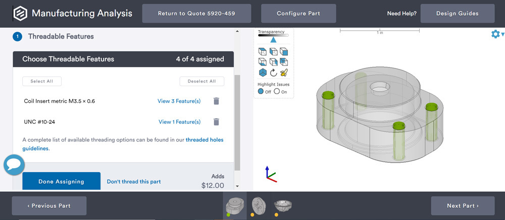
CNC Machining: Threaded Features
- Easily highlight and assign which holes need threads by clicking on 3D model (vs. choosing from list of holes)
- Immediately see the cost implications
- Limited selection of UNF, UNC, and metric threads along with coil and key inserts
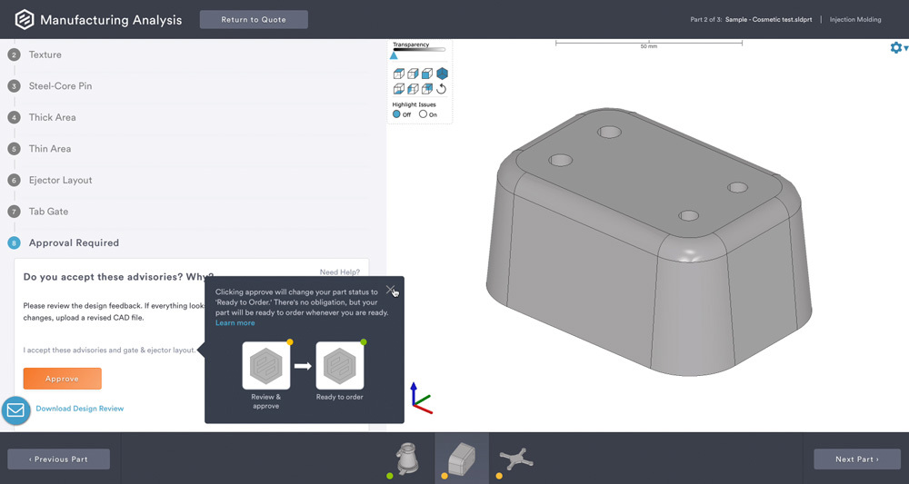
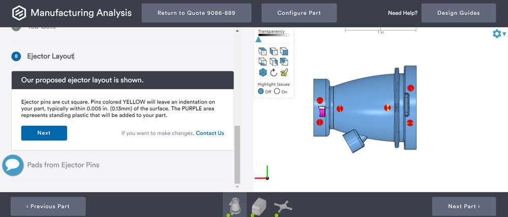
Molding: Gate & Ejector Pin Layout
- A gate and ejector pin layout design review on molded parts directly within your manufacturing analysis is now available before you place your order. Within your manufacturing analysis, you’ll be prompted to view Gate & Ejector Layout.
- Yellow and red indicate where it will be gated along with specific notes detailing the type of gate used where a small vestige may occur on the surface. Comment by clicking on a section of your 3D model or advance to the next step, which is your ejector pin placement.
- Yellow circles indicate where pins will be used to eject your parts from the mold. Comment on our recommended pin placement, which will be sent back to our team, or continue toward approval.
- Finally, you can download a PDF design review to look over and check the approval box.
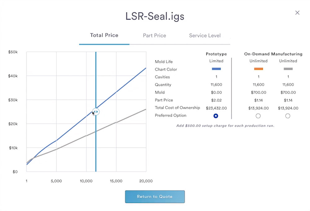
Molding: Tooling Options
- When requesting a quote, you’ll have the opportunity to choose the mold life of your tooling—limited or unlimited. Or choose I’ll Decide Later and we’ll work with you to identify the best tooling option.
- With unlimited, you’ll move into our on-demand manufacturing (ODM) option where you can also select sample quantity and identify whether you’ll need a single-cavity mold or multi-cavity mold (up to 8 cavities).
- Our Price Curve Tool compares tooling options to give you full visibility and total cost of ownership on molded parts.
Molding: Protolabs Proposed Revisions (PPR)
- Suggested PPR modifications to part geometry ensure your design complies with the capabilities of our digital manufacturing process and are intended to help improve part design and material selection.
- If you have required part changes, we’ll send you an already-revised model that you can review within your manufacturing analysis.
- Generally, we’ll provide STEP, IGES, and SolidWorks files depending on your original CAD model.
- You will have 3 options:
- Changes Accepted
- Changes Accepted, but you want to order from your own source file.
- Changes Not Accepted
![]() Note: PPRs are free and revised geometries are priced as any part would be. Some changes will influence price up or down. Most price changes from minor geometry revisions are negligible.
Note: PPRs are free and revised geometries are priced as any part would be. Some changes will influence price up or down. Most price changes from minor geometry revisions are negligible.