


5 Design Tips for Sheet Metal Assemblies
Streamline quoting and manufacturing to ensure you get the fastest response and shortest lead times possible.
By James Annis, Protolabs Engineering Technician
Unlocking access to quick turn prototype sheet metal assemblies is the key to keeping your project on time and within budget. While Protolabs sheet metal has a fantastic team of applications engineers ready to walk you through your design, the key to rapid quoting and manufacturing is keeping a few important assembly design tips in mind.
Mating Components: Mind the Gap!
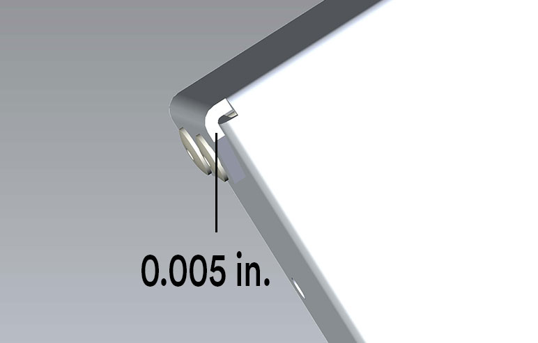
Sheet metal tolerances are significantly looser than those for standard machined parts, which have a tolerance of +/-0.005 in. (+/-0.127mm). In fact, if you are crossing multiple bends with your dimension the tolerance could be as loose as +/-0.030 in. (+/-0.762mm).
For example, when you are designing components that will be riveted together, it's important to think about this tolerance range and afford design accommodations, preventing components that can't mate because of interfering tolerances once fabricated. This mindful design philosophy will make the assemblers job quicker and easier with fewer opportunities for quality failures and non-conforming product.
A good rule of thumb is to allow for 0.005-0.010 in. (0.127-0.254mm) between your components. Also keep in mind that powder coating adds 0.002-0.005 in. (0.051-0.127mm) to your material thickness. So, if your parts are powder-coated, lead towards the large end of the gap range.
If that baseline separation between components is present, our programming department will do their best to adjust the geometry and maintain your original design. Lastly, following gap guidelines will reduce potential design-for-manufacturing (DFM) issues identified by our automation software, preventing additional processing time for your quote as well as when we get started on your order.
Design for Tooling and Hardware Access
Tooling and equipment such as welding torches, hardware installation tools, and spot welders need to have access to the areas of that part where the feature is being added. We have a variety of tools available to work through complex situations, but by going just a bit further to ensure the assembly is easy, simple, and straightforward, you can save on cost and time.
PEM hardware is installed with tooling on both sides of the hardware. that means we need direct access up and down from the hardware. If you must design a return flange over a piece of installed hardware, add a 0.75 in. (19.05mm) hole to accommodate hardware tooling. Asking yourself, "How would I install this hardware?" will take you far in designing a manufacturing-ready assembly that is easy to quote and produce.
MIG/TIG torches and pop riveting machines both need substantial room to operate. To simplify manufacturing and quoting, design your assembly to utilize welds and rivets installed from the exterior of the part. This will allow us to grind your welds to a nice finish, substantially reducing setup and run time and ensuring your project can be assembled quickly without creating unnecessary quality concerns.
Spot welders, just like PEM hardware, need access to both sides of the weld location for proper functionality. This means that your assembly must be designed in such a way that provides easy access to each component that will be spot-welded and should have a minimum flange length of 0.625 in. (15.875mm) to accept the spot welt tips that come together to fuse your parts.
Hand/assembly tool access It is easy to lose sight of the size and accessibility of fasteners and components during assembly after manufacture. Think about how you will install your loose hardware and components when designing your assembly after manufacture. Think about how you will install your loose hardware and components when designing your assembly. This foresight could save you the cost and time associated with numerous revision cycles during which these details are overlooked. There's nothing worse than going to assemble a project for which you spend thousands of dollars, as well as development and manufacturing time, only to get stuck with a fastener you can't fit into its hole.
Consistency and Flexibility with Punch-form Tools
If your project requires multiple punch-form features, such as embosses, ribs, louvers, or others, try to use the same features throughout your assembly. This will reduce quoting time substantially and positively affect the setup and run time on the punch.
When you are designing your features, be as flexible as possible. Our sheet metal team has an immense library of on-hand tools/features. If you can allow us to use one of our on-hand tools, and keep that tool consistent throughout your assembly, you will save thousands of dollars on custom tooling and close to a week of lead time waiting for those tools to come in. This compounds with the existing lead time because punch-form tools must be in hand before manufacturing begins.
Avoid Thin Materials when MIG/TIG Welding
It may be tempting to save on weight by using thin material for your welded assembly. This can be a pitfall because decreasing material thickness in a welded assembly increases risk of heat-related deformation, in particular. If you must create a welded assembly with material thickness of less than 0.063 in. (1.6mm), consider spot- or plug-welding (or rivets, ideally) first.
If that is not an option, choose the least amount of welding that will be effective for your needs. This could mean opting for 1 in. (25.4mm) of weld every 6 in. (152.4mm) rather than a fully welded seam or joint. That nice, welded corner you are looking for won't be so nice when heat causes the sheet to oil can. Oil canning, in this case, is when deformation is introduced to the sheet because of the immense heat from the welding operation.
Don't Submit Models with Non-Fabricated Components
This tip is applied during the quoting process. It may be tempting to drop your complete assembly model into our digital quoting platform but that will cause the estimating process to grind to a halt. Our automated systems are unable to process non-sheet metal components or loose hardware, so when a model is received with wire and cable harnesses, printed circuit boards, and EFI gaskets, the automated support in our system stops and the assembly must be processed 100% by a human estimator.
If you feel it is critical that we understand the design intent of your assembly as it pertains to your non-fabricated components, submit that information in a print and provide a 3D model of the fabricated components and permanently installed fasteners (PEM and rivets) only. We want to be the first one to deliver your quote and execute your project, sending us only the relevant 3D data is the best way to work with our systems and secure an actionable quote and lead time quickly.
Following these design tips will help you design a project that is ready for manufacture, can be quoted rapidly, and synchronizes with our strengths and capabilities. We know your project is important and timelines are never generous, but we're here to be your partner in rapid innovation. Engineering your assembly with manufacturability in mind form the beginning will help set up a smooth transition into production.

If you have any issues getting your guide, click here to download.


