


Metal 3D Printing Materials: What to Know
A comparison of metal materials available for direct metal laser sintering (DMLS)
How are Metal 3D Printing Materials Produced?
The DMLS process has a long, historical arc. Needless to say, the idea of using a laser to melt beds of metal powder was beyond our ancestors in the ancient world. Humans first used metal powders to make parts 5,000 years ago in Egypt. The process they used, which is still used today, is called powder metallurgy. It starts with pouring metal powder into a mold, packing it down to form the net shape and get the powder to stick together. With enough heat and/or pressure, particles want to reduce the amount of surface area they take up which causes them to meld together, resulting in sintering.
Now, let’s explore how the powders are made today using gas atomization. In this process, a stream of liquid metal is directed into a high-pressure blast of gas which breaks the metal up into small droplets. Basically, you end up with a metal mist that solidifies quickly into round particles of powder.
The process is similar to how Dippin’ Dots are made. To get the nice spheres of ice cream, the mix drips into a chamber full of liquid nitrogen to make the spheres. The biggest benefit of using gas atomization to create the raw material for additive manufacturing is that it offers the highest consistency of sphericity and particle size. That enhances flowability and creates a nice, level bed of powder to draw on with a laser.
Knowing how the powder is made is just the first step in the process. The actual printing method has changed over the years. In the earliest days of experimentation with 3D-printed metals, engineers used selective laser sintering (SLS) which worked with a similar principle to powder metallurgy. However, instead of needing to make a mold, operators used computers to control a laser to sinter the powder.
The downside to this process, as well as for powder metallurgy, is that it leaves micro-gaps, or pores, in the parts, making them less robust and less mechanically sound. These parts frequently require post-processing to reduce the size of those micro-gaps and enhance part performance.

DMLS parts, still on their build plate, are taken out of the metal powder from which they were manufactured.
Demystifying the DMLS Process
Today, manufacturers create metal 3D-printed parts using direct metal laser sintering (DMLS), although you’ll also hear the phrase direct metal laser melting (DMLM). The DMLS machine melts each layer—first the support structures to the base plate, then the part itself—with a laser aimed onto a bed of metallic powder. But in this case, the laser is completely melting the powder into a liquid, as opposed to sintering during which no melting occurs. Once a single layer of powder is micro-welded, the build platform shifts down and a re-coater blade moves across the platform to deposit the next layer of powder into the build chamber. The process is repeated layer-by-layer until the build is complete.
As discussed previously, DMLS removes that post-processing process. Once the print is completed, finished DMLS parts undergo the following:
- Parts are brushed manually to remove most of the loose powder.
- While still fixtured in the support system, parts are put through a heat-treat cycle to remove stresses.
- Parts are removed from the platform and their support structures are separated.
- Parts are then finished with any needed bead blasting and/or deburring.
Final DMLS parts are nearly 100% dense—that’s a substantial improvement over the SLS metal parts of the 1990s. Other specialized treatment options are available—more details on those later.
Still, there are quality considerations when your parts are removed from the printer, and a few solutions to help improve the mechanical and aesthetic properties of the final product.
Often, parts come out of the printer feeling slightly rough. That’s caused by the process itself. When a layer of powder is sintered to a part, you get a sort of gradient from totally melted near the part itself to an area where not everything in the new layer sinters.
Machining, polishing, or bead-blasting can take care of these issues, though. While DMLS achieves nearly 100% density, using hot isostatic pressing (HIP) further reduces any remaining porosity. More about HIP later. That said, if the slightly lower tensile strength on the Z-axis is a concern, you can “thicken up” areas in that plane.
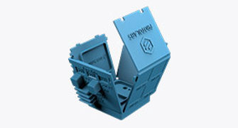
![]() Safely Working with Metal Powders
Safely Working with Metal Powders
One final consideration is the issue of non-reactive vs. reactive materials. Alloys made from either titanium, Inconel, or cobalt chrome are all highly reactive. They require specialized printing environments filled with argon gas to avoid exposure to oxygen and nitrogen which can cause gas pockets, roughness, and lesser mechanical properties. They are also more likely to throw off small bits of molten metal that can cause issues with surface finish. On the other hand, non-reactive materials such as the two stainless steels and low-oxygen titanium are much more stable and are less prone to corrosion. They are printed while surrounded by nitrogen gas.
Metal 3D Printing Materials Overview
Protolabs offers six types of metals for DMLS: aluminum, cobalt chrome, Inconel 718, titanium, and two types of stainless steel, 17-4 PH and 316L. Here’s a quick comparison of each. Note that the specifications for each metal vary dependent on printing resolution and how the material was conditioned. A more detailed chart is available, too.
| Materials | Resolution | Condition | Ultimate Tensile Strength (ksi) | Yield Stress (ksi) | Elongation (%) | Hardness |
|---|---|---|---|---|---|---|
| Stainless Steel (17-4 PH) | 20-30 μm | Solution & Aged (H900) | 198-199 | 178-179 | 13 | 42 HRC |
| Stainless Steel (316L) | 20-30 μm | Stress Relieved | 565-586 | 379-386 | 75-78 | 88-90 HRB |
| Aluminum (AlSi10Mg) | 20-40 μm | Stress Relieved | 268-345 | 180-228 | 8-15 | 42-59 HRB |
| Cobalt Chrome (Co28Cr6Mo) | 20-30 μm | As Built | 1213-1255 | 772-820 | 14-17 | 38-39 HRC |
| Inconel 718 | 20-60 μm | Stress Relieved | 958-993 | 572-676 | 36-40 | 27-33 HRC |
| 30-60 μm | Solution & Aged per AMS 5663 | 1386-1434 | 1200-1207 | 18-19 | 45-46 HRC | |
| Titanium (Ti6Al4V) | 20-30 μm | Stress Relieved | 993-1055 | 855-951 | 15-18 | 33-35 HRC |
*20 μm = high resolution (HR)
*30, 40, and 60 μm = normal resolution (NR)
These figures are approximate and dependent on a number of factors, including but not limited to, machine and process parameters. The information provided is therefore not binding and not deemed to be certified. When performance is critical, also consider independent lab testing of additive materials or final parts.
| Materials | Resolution | Condition | Ultimate Tensile Strength (ksi) | Yield Stress (ksi) | Elongation (%) | Hardness |
|---|---|---|---|---|---|---|
| Stainless Steel (17-4 PH) | 20-30 μm | Solution & Aged (H900) | 198-199 | 178-179 | 13 | 42 HRC |
| Stainless Steel (316L) | 20-30 μm | Stress Relieved | 82-85 | 55-56 | 75-78 | 88-90 HRB |
| Aluminum (AlSi10Mg) | 20-40 μm | Stress Relieved | 39-50 | 26-33 | 8-15 | 42-59 HRB |
| Cobalt Chrome (Co28Cr6Mo) | 20-30 μm | As Built | 176-182 | 112-119 | 14-17 | 38-39 HRC |
| Inconel 718 | 20-60 μm | Stress Relieved | 139-144 | 83-98 | 36-40 | 27-33 HRC |
| 30-60 μm | Solution & Aged per AMS 5663 | 201-208 | 174-175 | 18-19 | 45-46 HRC | |
| Titanium (Ti6Al4V) | 20-30 μm | Stress Relieved | 144-153 | 124-138 | 15-18 | 33-35 HRC |
*20 μm = high resolution (HR)
*30, 40, and 60 μm = normal resolution (NR)
These figures are approximate and dependent on a number of factors, including but not limited to, machine and process parameters. The information provided is therefore not binding and not deemed to be certified. When performance is critical, also consider independent lab testing of additive materials or final parts.
Your materials choice fundamentally affects the outcome of your parts, so it helps to have a general understanding of the advantages of each material available for your project. Here’s a description of each:
Aluminum (AlSi10Mg) is comparable to the 3000 series alloy that is used in casting and die casting processes. It has good strength-to-weight ratio, high temperature and corrosion resistance, and good fatigue, creep and rupture strength. AlSi10Mg also exhibits thermal and electrical conductivity properties. Final parts built in AlSi10Mg receive stress relief application. Suitable industries: Aerospace and automotive, consumer goods, manufacturing, and construction.
Cobalt Chrome (Co28Cr6Mo) is a superalloy known for its high strength-to-weight ratio. It has high-performance tensile and creep characteristics and strong corrosion resistance. Suitable industries: Medical and dental, aerospace, industrial manufacturing, and jewelry.
Inconel 718 is a high strength, corrosion resistant nickel-chromium superalloy ideal for parts that will experience extreme temperatures and mechanical loading. Final parts built in Inconel 718 receive a stress relief application. Solution and aging per AMS 5663 are also available to increase tensile strength and hardness. Suitable industries: Aerospace, energy, chemical processing, marine.
Stainless Steel 17-4 PH is a precipitation-hardened stainless steel that is known for its hardness and corrosion resistance. If you need to use stainless steel, select 17-4 PH for its significantly higher tensile strength and yield strength, but recognize that it has far less elongation at break than 316L. Final parts built using 17-4 PH receive vacuum solution heat treatment as well as H900 aging. Suitable industries: Aerospace, automotive, medical and dental, oil and gas, chemical processing, marine.
Stainless Steel 316L is a workhorse material used for manufacturing acid- and corrosion-resistant parts. Select 316L when stainless steel flexibility is needed as it is a more malleable material compared to 17-4 PH. Final parts built in 316L receive a stress relief application. Suitable industries: Medical and dental, food and beverage, chemical processing and pharmaceuticals, marine, oil and gas, jewelry, consumer goods.
Titanium (Ti6Al4V) is a workhorse alloy. Compared to Ti grade 23 annealed, the mechanical properties of Ti6Al4V are comparable to wrought titanium for tensile strength, elongation, and hardness. Final parts built in Ti6Al4V receive a vacuum stress relief application. Suitable industries: Aerospace and defense, medical and dental, automotive, consumer goods, bioprinting.
Here’s a quick overview to help you find just the right metal based on various qualities.
| Aluminum (AlSi10Mg) | Cobalt Chrome (Co28Cr6Mo) | Inconel 718 | Stainless Steel (17-4 PH) |
Stainless Steel (316L) | Titanium (Ti6Al4V) | |
|---|---|---|---|---|---|---|
| Corrosion Resistance | X | X | X | X | X | |
| Dimensional Stability | X | X | X | X | X | X |
| Durability | X | X | X | |||
| Large Format | X | X | ||||
| Lightweight | X | X | ||||
| Strength | X | X | X | X | ||
| Strength-to-Weight | X | X | ||||
| Stiffness | X | X | X | X | X | |
| Temperature Resistance | X | X | X |
Surface Roughness and Finishing of Metal 3D-Printed Parts
The rapid heating and cooling of the metal material during the DMLS process results in a buildup of internal stresses. While every build undergoes a stress relief treatment per the ASTM 3301 standard, additional heat treatments can further improve mechanical properties like hardness, elongation, fatigue strength, and more.
Hot Isostatic Pressing (HIP)
This process combines high pressure and temperature to eliminate any potential porosity within the part and reduce anisotropy. It also increases resistance to impact, wear, and abrasion, and improves fatigue characteristics. Typically, HIP is used for aerospace components that will be under heavy loads. HIP reduces much of the remaining internal micro-porosity by exposing the part to 2,000° F (1093° C) heat and very high pressure of 15,000psi (103.42 MPa) on all sides to fully solidify the part.
Solution Annealing
The workpiece is heated above its recrystallization temperature and then cooled rapidly to relieve stresses and remove small imperfections in the microstructure. This is often used for stainless steel parts as it reduces hardness and increases ductility.
Aging
This is a secondary heat treatment process applied to certain metal alloys. Part temperature is elevated and held for a designated time, causing precipitate formation. Our standard process is to age 17-4 stainless steel to the H900 condition. By request, Inconel 718 may be aged to boost temperature resistance, strength, and hardness properties.
While these heat-based processes address the mechanical properties of the part, another important concern with 3D printing is surface roughness. The most widely used measure of surface roughness is Ra, or the average roughness between a roughness profile and the mean line. Ra is the deviation from the ideal surface plane measured in microinches or micrometers. A larger Ra unit equates to a rougher surface.
Protolabs DMLS parts have a 200-400 microinch (5.08-10.16µm) Ra with standard finishing and 400-600 (10.16-15.24µm) as-printed. The difference in finish between our normal and high resolution is small. Polishing and machining are available to improve on the as-printed values noted above.

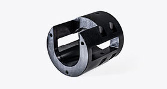
As with all DMLS parts, this polished titanium bracket approaches 100% density.
Density, Weight, and Strength of Metal Printed Parts
There are two ways to think about density. The first is the mass of the material compared to the volume it occupies. Many times, material density is expressed in grams per cubic centimeter (g/cc).
The density of a metal will determine how much a part of a particular size weighs, and of course weight is an important consideration, especially in aerospace and automotive applications. Engineers and designers in those industries are always looking for ways to reduce component weight to meet emission standards, cut fuel consumption, consolidate many parts into fewer parts, and streamline overall product design.
Dense materials make strong parts—the higher the density, the greater the strength—which is why the percentage of density of a part’s material is so crucial. Density is essentially the concentration of a given material in a given space.
Engineers and designers looking for lower-weight parts might turn to materials or alloys that are less dense. You should be cautious, though, because then you must consider the strength-to-weight ratio, too.
Topology optimization is a critical tool for removing weight while making sure that the part still has the required strength. It works by identifying which areas of the part see the highest loads, and which see little to no load and can therefore be removed. Often, this leads to organically shaped parts that would be hard to make with traditional methods like machining. Thankfully 3D printing makes these shapes possible.
Topology optimization is used today across many industries and at varying levels of scale. For example, the University of North Carolina Formula BAJA team used topology optimization to remove precious ounces from the team’s car by carefully light-weighting the sway bar responsible for preventing rollover during a race. Of course, strength was critical in the part, but removing unnecessary weight could help the team reach top speeds. On a larger scale, aerospace companies are reducing weight in components as small as brackets to save millions of gallons in fuel annually.
The other way to think about density is in terms of porosity, or lack thereof. This is typically expressed as % density or % porosity. The DMLS process generally produces parts that are nearly 100% dense, although a small amount of porosity is typically present. We expect our DMLS parts to meet or exceed 99.5% density through our standard process. For applications that require the highest mechanical performance and fatigue resistance, the small amount of porosity present in a printed component can be reduced even further through hot isostatic pressing (HIP).
All metal additive parts, including those made using DMLS, can undergo radiographic testing to ensure porosity is minimal. X-ray scanning is a common choice for both metal additive parts and cast parts. The key benefit is that you can inspect the inside of the part for porosity without destroying it. Non-destructive radiographic inspection ensures that metal additive parts are free from the pores that could cause cracking while the part is in use.

Designing multiples of the same part for a single build plate can save time and money.
Comparing Printed and Machined Metals
Sometimes your designs give you the option to choose between 3D printing and CNC machining. Each has its own advantages, but we’re here to focus on materials and how the manufacturing process affects them, if both can handle the geometries of your design:
3D printing offers:
- Potentially lesser mechanical properties compared to CNC machined parts, as they are typically not fully isotropic.
- Metals that would be difficult to machine (superalloys, in particular) can be 3D-printed.
CNC machining characteristics:
- Excellent mechanical and thermal properties with fully isotropic behavior, meaning that the properties remain the same when tested in different directions.
- Dimensional restrictions from material blank or block sizes (using a non-standard blank size increases the manufacturing cost).
- A wide range of production-grade materials from which to choose.
Key material properties can also vary slightly between the two processes. A few comparisons of popular metals include:
Comparing materials that are available via both our 3D printing and CNC machining services (both stainless steels and titanium), you’ll find that, in general, the printed parts have somewhat better elongation, hardness, and tensile strength.
The process you choose also affects the surface finish of your parts. Parts produced by both of these manufacturing processes can initially come out a bit rough. Those parts built by machining can come out, as some in the industry call it, “as-machined” or “as-milled.” That means you’re going to see some surface roughness and blemishes. Those parts produced by 3D printing will have more surface roughness or graininess, resembling the texture of a cast iron frying pan.
Fortunately, you can improve functionality and aesthetics of manufactured parts with a variety of post-process finishing options.
Several post-process options for machining can help protect parts and improve overall finish. Common processes include plating, anodizing, powder coating or painting, and more. Many of these processes can also be applied to metal additive parts.
For 3D printing, depending on the additive manufacturing technology, build direction, resolution, and materials chosen, you might see issues with part aesthetics. Here’s a quick look at the 3D printing finishing options commonly offer and what you can expect as a result:
- Standard: Supported surfaces are sanded, and the entire part is finely blasted for a consistent look.
- Custom Hand Polishing: Parts undergo hand-sanding to achieve the desired finish. Finishes from a “machined surface” to near mirror finish are attainable. This is suitable for cosmetic surface finish improvements.
- Post Machining: In addition to a wealth of other machining operations, surfaces that need functional smoothness, such as sealing grooves, can be post machined.
Here’s something you may want to consider: Post-processing machining on 3D-printed parts lets you get the complexity that machining alone can’t achieve while ensuring critical features are to spec. It could be your ideal equation for metal manufacturing.
All in all, if you were to compare 3D metal-printed parts to any manufacturing process, casting would be the most appropriate. Both are based on a liquid turning into a solid and require designers to consider things like uniform wall thickness, avoiding sharp corners and more. The tensile strength of DMLS parts is generally as good or better than cast, but fatigue is worse. Using HIP, however, can address this issue.