


Selecting a Rapid Prototyping Process
Compare manufacturing technologies to find a process best suited to your needs.
Prototyping is the starting gate in the race to improve and perfect products. Each iteration refines your parts to ensure fit, form, and function. The good news is that there are dozens of ways prototypes can be made. Moreover, as new prototyping processes emerge, product designers have the opportunity to choose which process or technology is best for their unique application.
This guide explores the advantages and shortcomings of the major prototyping processes now available to designers. It provides process descriptions and discusses material properties of parts made from each prototyping option. Also, a helpful tree highlights the key questions designers must consider when choosing a prototyping process. Ultimately, we want to help you select the best prototyping process for your product’s development cycle.
What is Rapid Prototyping?
Rapid prototyping is a common early step within the product development process during which design teams quickly iterate an initial model. Often, this design will become a minimum viable product, or MVP, since it contains only the essential features necessary to test and gain user feedback. Typically, speed is most valuable during this phase of product development, so quick-turn or digital manufacturing processes like 3D printing or CNC machining are preferred. This allows product designers to test multiple iterations, or designs, within a short period of time and finalize their parts more quickly.
What are the Advantages of Rapid Prototyping?
Done right, rapid prototyping streamlines product development, providing wholly positive results.
Cost-Effectiveness
Here is an example: Traditional prototyping for injection molding often involves new tooling and molds for each iteration, but creating multiple, expensive steel molds to test a part may not be the best use of this technology. Rapid prototyping aims to save you money by altering that step. One way is to use injection molding with comparatively inexpensive aluminum molds, or prototyping using 3D printing, CNC machining, or sheet metal fabrication, depending on your part design. With any of these, you’ll be able to manufacture your prototype at a fraction of the cost. Depending on your needs, your final iteration can then use injection molding for high-volume production.
Enhanced Communication and Collaboration
Rapid prototyping typically involves digital manufacturing processes, which invite collaboration during the iteration phase, using a computer-based model of a part called a digital twin—a virtual version of a physical (or soon-to-be physical) part. The digital twin travels through a virtual version of the manufacturing floor, identifying potential manufacturability issues before the real work begins. Collective stakeholders can identify any issues in the digital version of the file, respond to that, and provide input before final manufacturing begins. Once a prototype has been manufactured, that physical object can be shared with others for their evaluation.
Accelerate Product Development
When prototyping, you want to use the fastest manufacturing method available to make your parts. That decision will be informed by your end part, but if you just need a part manufactured for which you can test form, fit, and function, it helps to choose the simpler/faster process to enhance iteration speed. As mentioned above, there are solutions that not only speed development, but also reduce costs.
Greater Product Customization
Rapid prototyping allows for fast tweaks to design so you can customize the parts you need. Whether you intend to offer end users variations of color, material, or functionality, this method will speed manufacturing of individual parts for evaluation.
Improved Design Validation
No one wants to go to full production quantities without proper testing and validation. At the core of rapid prototyping is a process that can detect flaws early in the development process, either via user feedback or functional testing. This can help avoid issues later in your product’s life cycle.
Ways to Reduce the Cost of Rapid Prototyping
Something not often thought about is the fact that rapid prototyping gets you your parts faster. That reduces costs because you avoid the expense of waiting for parts and reduce go-to-market delays. Here are some additional ways to reduce costs:
Use a Digital Manufacturer
Using a digital manufacturer moves your parts from CAD model to prototype faster than traditional manufacturers. It also has the bonus of offering design for manufacturing (DFM) feedback to ensure that your part doesn’t have issues that would prevent it from being manufactured.
Choose Materials Wisely
Remember, it’s just a prototype. This isn’t your final part. Let’s say your final product needs to be made in an expensive material, such as titanium. If all you need is to confirm basic specifications and fit, any other metal (or in some cases, even plastics) will work well when evaluating part design.
Drop Surface Finishes
Typically, these are aesthetic or protective coatings that simply are not necessary at this stage. Unless you need to validate the fit of a finished part within your application, eliminating finishes and other secondary operations such as smoothing on prototypes will save you money and time.
Evaluate Your Design
Think about the elements of each part that are most crucial to you and concentrate on nailing those down. Before prototyping, it helps to have a goal regarding what you would consider a minimum viable prototype (MVP). The MVP allows you to properly evaluate how your part works within the context of your application. Aim for that and you will likely have greater success more quickly.
Comparing Prototyping Processes
| Process | Description | Finish | Example Materials | |
|---|---|---|---|---|
| SLA | Stereolithography | Laser-cured photopolymer |
Additive layers of 0.002-0.006 in. (0.051-0.152mm) typical, 0.004 in. (0.1016mm) maximum layer thickness |
Thermoplastic-like photopolymers |
| SLS | Selective Laser Sintering | Laser-sintered powder | Additive layers of 0.004 in. (0.102mm) typical | Nylon, TPU |
| DMLS | Direct Metal Laser Sintering | Laser-sintered metal powder | Additive layers of 0.0008-0.0012 in. (0.020-0.030mm) typical | Stainless steel, titanium, chrome, aluminum, Inconel |
| FDM | Fused Deposition Modeling | Fused extrusions | Additive layers of 0.005-0.013 in. (0.127-0.330mm) typical | ABS, PC, PC/ABS, PPSU |
| MJF | Multi Jet Fusion | Inkjet array selectively fusing across bed of nylon powder |
Additive layers of 0.0035-0.008 in. (0.089-0.203mm) typical, only 0.00315 in. (0.080mm) offered |
Black Nylon 12 |
| PJET | PolyJet | UV-cured jetted photopolymer |
Additive layers of 0.0006-0.0012 in. (0.015-0.030mm) typical, only 0.0012 in. (0.030mm) layers offered |
Acrylic-based photopolymers, elastomeric photopolymers |
| CNC | Computer Numerically Controlled Machining | Machined using CNC mills and lathes | Subtractive machined (smooth) | Most commodity and engineering-grade thermoplastics and metals |
| IM | Injection Molding | Injection-molded using aluminum tooling | Molded smooth (or with selected texture), including industrial standard finishes such as SPI grades and Mold-Tech | Most commodity and engineering-grade thermoplastics, metal, and liquid silicone rubber |
| SM | Sheet Metal Fabrication | Conventional press brake sheet metal fabrication including permanent hardware, and welding | Orbital sanded or straight grain brushed, and “#4” (304-#4 stainless) | Aluminum, stainless, steel, copper, brass, and more |
Pros and Cons of Each Prototyping Process
3D Printing Processes
| SLA | Stereolithography | |
|---|---|---|
| SLA is an industrial 3D printing, or additive manufacturing, process that builds parts in a pool of UV-curable photopolymer resin using a computer controlled laser. The laser is used to trace out and cure a cross-section of the part design on the surface of the liquid resin. The solidified layer is then lowered just below the surface of the liquid resin and the process is repeated. Each newly cured layer adheres to the layer below it. This process continues until the part is completed. | ||
| Pros For concept models, cosmetic prototypes, and complex designs, SLA can produce parts with intricate geometries and excellent surface finishes as compared to other additive processes. Cost is competitive and the technology is available from several sources. |
Cons Prototype parts may not be as strong as those made from engineering-grade resins, so the parts made using SLA have limited use for functional testing. Additionally, while parts undergo a UV-cycle to solidify the outer surface of the part, parts built in SLA should be used with minimal UV and humidity exposure so they don’t degrade. |
|
| SLS | Selective Laser Sintering | |
|---|---|---|
 |
SLS is one of five additive processes available at Protolabs. During the SLS process, a computer-controlled CO2 laser draws onto a hot bed of nylon-based powder from the bottom up, where it lightly sinters (fuses) the powder into a solid. After each layer, a roller lays a fresh layer of powder on top of the bed and the process repeats. SLS uses either rigid nylon or elastomeric TPU powders similar to actual engineering thermoplastics, so parts exhibit greater toughness and are accurate, but have rough surface and lack fine details. SLS offers a large build volume, can produce parts with highly complex geometries and create durable prototypes. | |
| Pros SLS parts tend to be more accurate and durable than SLA parts. The process can make durable parts with complex geometries, and is suitable for some functional testing |
Cons The parts have a grainy or sandy texture and the process has a limited resin choice. |
|
| DMLS | Direct Metal Laser Sintering | |
|---|---|---|
 |
DMLS is an additive manufacturing technology that produces metal prototypes and functional, end-use parts. DMLS uses a laser system that draws onto a surface of atomized metal powder. Where it draws, it welds the powder into a solid. After each layer, a blade adds a fresh layer of powder and repeats the process. DMLS can use most alloys, allowing prototypes to be full-strength, functional hardware made out of the same material as production components. It also has the potential, if designed with manufacturability in mind, to transition into metal injection molding when increased production if needed. | |
| Pros DMLS produces strong (typically, 97 percent dense) prototypes from a variety of metals that can be used for functional testing. Since the components are built layer by layer, it is possible to design internal features and passages that could not be cast or otherwise machined. Mechanical properties parts are equal to conventionally formed parts. |
Cons If producing more than a few DMLS parts, costs can rise. Due to the powdered metal origin of the direct metal process, the surface finish of these parts are slightly rough. The process itself is relatively slow and also usually requires expensive post-processing. |
|
| FDM | Fused Deposition Modeling | |
|---|---|---|
 |
FDM uses an extrusion method that melts and re-solidifies thermoplastic resin (ABS, polycarbonate, or ABS/polycarbonate blend) in layers to form a finished prototype. Because it uses real thermoplastic resins, it is stronger than binder jetting and may be of limited use for functional testing. | |
| Pros FDM parts are moderately priced relatively strong, and can be good for some functional testing. The process can make parts with complex geometries |
Cons The parts have a poor surface finish, with a pronounced rippled effect. It is also a slower additive process than SLA or SLS and has limited suitability for functional testing. |
|
| MJF | Multi Jet Fusion | |
|---|---|---|
| MJF uses an inkjet array to selectively apply fusing and detailing agents across a bed of nylon powder, which are then fused by heating elements into a solid layer. After each layer, powder is distributed on top of the bed and the process repeats until the part is complete. When the build finishes, the entire powder bed with the encapsulated parts is moved to a processing station where a majority of the loose powder is removed by an integrated vacuum. Parts are then bead blasted to remove any of the remaining residual powder before ultimately reaching the finishing department where they are dyed black to improve cosmetic appearance. | ||
| Pros MJF is fast—producing functional nylon prototypes and end-use production parts in as fast as one day. Final parts exhibit quality surface finishes, fine feature resolution, and more consistent mechanical properties when compared to processes such as SLS. |
Cons Currently MJF is limited to PA12 nylon, and SLS has better small feature accuracy (small feature tolerances). |
|
| PJET | PolyJet | |
|---|---|---|
| PolyJet uses a print head to spray layers of photopolymer resin that are cured, one after another, using ultraviolet light. The layers are very thin allowing quality resolution. The material is supported by gel matrix that is removed after completion of the part. Elastomeric parts are possible with PolyJet. | ||
| Pros This process is moderately priced, can prototype overmolded parts with flexible and rigid materials, can produce parts in multiple color options, and easily duplicates complex geometries. |
Cons PolyJet parts have limited strength (comparable to SLA) and are not suitable for functional testing. While PolyJet can make parts with complex geometries, it gives no insight into the eventual manufacturability of the design. Also, colors can yellow when exposed to light over time. |
|
| HPS | Hybrid PhotoSynthesis | |
|---|---|---|
 |
HPS technology integrates both a precision laser and a digital light processing (DLP) system to simultaneously image internal and external structures. This dual approach allows the Axtra3D printer to overcome traditional limitations and produce exceptionally detailed parts with unmatched speed and quality. | |
| Pros |
Cons |
|
CNC Machining
| CNC | Computer Numerically Controlled Machining | |
|---|---|---|
| In machining, a solid block (or rod stock) of plastic or metal is clamped into a CNC mill or lathe respectively and cut into a finished part through a subtractive process. This method generally produces superior strength and surface finish to any additive manufacturing process. It also has the complete, homogenous properties of the plastic because it is made from solid blocks of extruded or compression molded thermoplastic resin, as opposed to most additive processes, which use plastic-like materials and are built in layers. The range of material choices allows parts to be made with the desired material properties, such as: tensile strength, impact resistance, heat deflection temperatures, chemical resistance, and biocompatibility. Good tolerances yield parts suitable for fit and functional testing, jigs and fixtures, and functional components for end-use applications. A number of manufacturers, including Protolabs, use 3-axis milling and 5-axis indexed milling processes along with turning to manufacture parts in a range of engineering-grade plastics and metals. | ||
| Pros Machined parts have good surface finishes and are quite strong because they use engineering-grade thermoplastics and metals. As with 3D printing, custom prototypes can be delivered in as fast as one day due to our proprietary automated processes. |
Cons There may be some geometry limitations associated with CNC machining, and it is sometimes more expensive to do this in-house rather than 3D printing processes. Because the process is removing material instead of adding it, milling undercuts can sometimes be difficult and part design should be carefully considered for ease of manufacturing. |
|
Injection Molding
| IM | Injection Molding | |
|---|---|---|
| Rapid injection molding works by injecting thermoplastic resins into a mold, just as in production injection molding. What makes the process “rapid” is the technology used to produce the mold, which is often made from aluminum instead of the traditional steel used in production molds. Molded parts are strong and have excellent finishes. It is also the industry standard production process for plastic parts, so there are inherent advantages to prototyping in the same process if the situation allows. Almost any engineering-grade plastic or liquid silicone rubber (LSR) can be used, so the designer is not constrained by the material limitations of the prototyping process. | ||
| Pros Molded parts are made from an array of engineering-grade materials, have excellent surface finish, and are an excellent predictor of manufacturability during the production phase. |
Cons There is an initial tooling cost associated with rapid injection molding that does not occur with any of the additive processes or with CNC machining. So in most cases, it makes sense to do one or two rounds of rapid prototypes (subtractive or additive) to check fit and function before moving to injection molding. |
|
Sheet Metal Fabrication
| SM | Sheet Metal Fabrication | |
|---|---|---|
 |
Conventional press brake forming processes rapidly produce both simple and complex forms. Laser and punch cutting cut geometries and can include punch form features up to 4 in. (101.6mm) in most cases, with longer features available using progressive punch tooling. Protolabs combines this cutting and forming capability with permanent hardware installation including clinch fasteners like those Penn Engineering (PEM) offers, as well as resistance-welded studs and nuts. Highly skilled assemblers are ready to weld or rivet your final designs, as well as finish your parts with in-house powder coating and silkscreen capabilities. | |
| Pros Most sheet metal geometries can be produced with high precision in a vast array of thicknesses and material types. |
Cons Sheet metal is limited in its ability to produce stamped features, and features requiring curved or organic-shaped bend lines. Press brake forming can produce linear bends with an inside bend radius of approximately 0.010 in. (0.25mm) and up. |
|
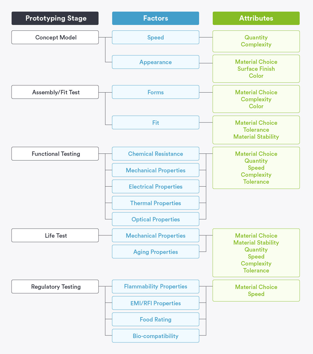
Choosing a Process
Use the decision tree below to narrow down which factors are of highest importance to you based on where you are in the prototyping process, referring as needed to the definitions below this decision tree infographic.
Rapid Prototyping Applications
Definitions vary and may differ at different organizations, but the definitions below may be used as a starting point.
Concept Model
A physical model made to demonstrate an idea. Concept models allow people from different functional areas to see the idea, stimulate thought and discussion, and drive acceptance or rejection.
Prototyping Considerations
- Speed: turnaround time to convert a computer file into a physical prototype
- Appearance: any visual attribute: color, texture, size, shape, etc.
Assembly/Fit Testing
Manufacturing some or all parts of an assembly, putting them together, and seeing if they fit properly. At the gross level, this checks for design errors, such as placing two tabs at 2 in. (50.8mm) spacing and the mating slots at 1 in. (25.4mm) spacing. At the fine level, this is a matter of minor dimensional differences and tolerances. Obviously, any test involving tolerances needs to use the actual manufacturing process or one which has similar tolerances.
Prototyping Considerations
- Form: the shape of the part; features and size
- Fit: how the part mates with other parts
Functional Testing
Evaluating how a part or assembly will function when subjected to stresses representative of what it will see in its actual application.
Prototyping Considerations
- Chemical Resistance: resistance to chemicals including acids, bases, hydrocarbons, fuels, etc.
- Mechanical Properties: strength of the part measured by tensile strength, compressive strength, flexural strength, impact strength, tear resistance, etc.
- Electrical Properties: interaction of electrical fields with the part. This may include dielectric constant, dielectric strength, dissipation factor, surface and volume resistance, static decay, etc.
- Thermal Properties: changes in mechanical properties that occur with changes in temperature. These may include thermal expansion coefficient, heat deflection temperature, Vicat softening point, etc.
- Optical Properties: ability to transmit light. May include refractive index, transmittance, and haze.
Life Testing
Testing properties that may change with time and that are important for a product to remain functional throughout its expected life. Life testing often involves subjecting the product to extreme conditions (e.g., temperature, humidity, voltage, UV light, etc.) to estimate in a shorter period of time, how the product will react during its expected life.
Prototyping Considerations
- Mechanical Properties (fatigue strength): ability to withstand repeated load cycles at various stress levels.
- Aging Properties (UV, creep): ability to withstand exposure to ultraviolet light with an acceptable amount of degradation; ability to withstand extended applications of forces to the part with acceptable levels of permanent deflection.
Regulatory Testing
Testing specified by a regulatory or standards organization or agency to assure parts are suitable for a particular use such as a medical, food service, or consumer application. Examples include Underwriters Laboratory (UL), the Canadian Standards Association (CSA), the U.S. Food and Drug Agency (FDA), the U.S. Federal Communications Commission (FCC), the International Standard Organization (ISO) and the European Commission (EC).
Prototyping Considerations
- Flammability Properties: the resistance of a resin or part to ignition in the presence of a flame.
- EMI/RFI Properties: the ability of a resin, part or assembly to shield or block electromagnetic interference or radio frequency interference.
- Food Rating: approval of a resin or part to be used in applications when it comes in contact with areas where food is prepared, served or consumed.
- Biocompatibility: the ability of the resin or part to be in contact with human or animal bodies, outside or inside the body, without causing undue adverse effects (e.g., irritations, blood interactions, toxicity, etc.). Biocompatibility is important for surgical instruments and many medical devices.
Considerations for Transitioning to Production for Injection Molding During Prototyping
As mentioned earlier, many engineers use 3D printing for prototyping and then switch over to injection molding for production quantities. It makes sense in terms of cost and time saved. Industries including aerospace and medical device typically take this path during their product’s life cycle. So, how do you set yourself up for success moving from 3D printing to injection molding? Here is a basic overview but note that we also offer more detailed information.
Define Your Part Before Designing
It is important to put a lot of thought into a part’s design, being cognizant of the different DFM requirements that 3D printing and injection molding have. During prototyping, don’t box yourself into a corner with fancy geometries that print beautifully but can’t be replicated via injection molding. Our interactive DFM feedback during quoting can provide helpful guidance.
Beyond that, consider the environment your parts will need to withstand. Choose designs and materials that can survive whatever will be thrown at them.
Using Multiple Prototypes
Designing and manufacturing multiple prototypes enables you to explore different design options, features, or aesthetic variations without committing to the costly tooling for injection molding too early. This allows for a more comprehensive understanding of what works best for the intended application and market. It also speeds up the period of time necessary to evaluate different iterations.
Maneuvering Through Molding
Transitioning to injection-molded parts requires specific design methods such as uniform wall thickness and draft angles. Maintaining a uniform wall thickness ensures the mold fills evenly, preventing defects. Adding draft angles to the design facilitates the easy ejection of the part from the mold. These are considerations that must be included when moving to injection molding, even if not present in a 3D-printed prototype.
Choosing Materials
Even the same material can act differently when printed vs. molded. Material selection for injection molding depends on various properties, including mechanical, physical, and thermal characteristics. Manufacturability, including resin flow and how well it fills the mold features, is essential. Cosmetic appearance and cost also play significant roles in the material selection process.
Mitigating Costs and Timelines
Prototyping using 3D printing is often the fastest way to iterate. Changes can be made in a CAD model, leading to quick turnaround of your updated prototype. While cost and deadlines are crucial factors, using affordable production methods can help control costs. Digital manufacturing can also accelerate product development, shortening both prototyping and production timelines. This approach helps optimize the overall efficiency of the transition from prototyping to production.
Summary
Prototype models help design teams make more informed decisions by obtaining invaluable data from the performance of, and the reaction to, those prototypes. The more data that is gathered at this stage of the product development cycle, the better the chances of preventing potential product or manufacturing issues down the road. If a well thought out prototyping strategy is followed, there is a far greater chance that the product will be introduced to the market on time, be accepted, perform reliably, and be profitable.
What is the best way to get a prototype made? The answer depends on where you are in your process and what you are trying to accomplish. Early in the design process, when the ideas are flowing freely, concept models are helpful. As the design progresses, a prototype that has the size, finish, color, shape, strength, durability, and material characteristics of the intended final product becomes increasingly important. Therefore, using the right prototyping process is critical. In order to most effectively validate your design, pay close attention to these three key elements of your design: functionality, manufacturability, and viability.
If your prototype can faithfully represent the attributes of the end-product, it is by definition functional. These requirements often include such things as material properties (e.g., flame resistance), dimensional accuracy for fit-up with mating parts, and cosmetic surface finishes for appearance.
If your prototype design can be repeatedly and economically produced in a manner that supports the requirements of the end product, it is by definition manufacturable. These requirements include the ability to maintain the functionality of the design as described above, keep the piece-part cost below the required level, and support the production schedule. No matter how great a design is, it will go nowhere if it can’t be manufactured. Make sure your prototyping process takes this into consideration.
Finally, even if your prototype design is functional and manufacturable, it doesn’t mean anyone will want to use it. Prototypes are the only true way to verify the viability of the design in this sense. If your design can also pass the challenges associated with market trials (e.g., trade show displays, usability testing) and regulatory testing (e.g., FDA testing of medical devices), you’re well on your way to a successful product launch.