How Does 3D Printing or Additive Manufacturing Work?
Learn about additive manufacturing technologies, industry applications, and benefits from prototyping to production
A good starting point for 3D printing is to look at it as a process in which parts are built by adding material to form an object as opposed to subtracting it as is the case with CNC machining. Some people like to call it by its more formal name: additive manufacturing (AM), especially when linked to industrial-grade quality and production quantities but to be honest, most people just use the term 3DP, and often, so do we.
But who came up with such a cool idea? At first it was the stuff of science fiction. Arthur C. Clarke, author, came up with the general premise behind 3D printing in 1964. It would be another 20 years before legit 3D printing came on the scene, thanks to Chuck Hull. He patented the stereolithography (SLA) process, which uses lasers to solidify layers of thermoset resin. That invention marked the true start of today's additive manufacturing. Seeing the potential for a growth industry, in 1986 Hull founded 3D Systems. A year later, the company released the SLA-1, the world’s first commercially available SLA printer.
One of the earliest uses of stereolithography was in rapid prototyping, where it was used to quickly create physical prototypes of new parts and products. This allowed designers and engineers to test their designs more quickly and cost-effectively than with traditional manufacturing methods.
Fused deposition modeling (FDM), which captured the hearts of desktop hobbyists worldwide, came along in 1988, the same year the first patent for selective laser sintering (SLS) was awarded. More on those and other processes later.

So, beyond the cool factor, what’s up with the love affair with 3D printing? Well, compared to traditional processes 3D printing has a lot going for it. It lets you:
- build complex, organic geometries and internal features with limited effect on part cost
- consolidate multi-component assemblies into a single part
- avoid upfront tooling (mold) costs
- speed production to get your parts fast
One fundamental advantage of 3D printing is that it allows for rapid iteration. You can get a “first draft” part one day, find something you’d like to tweak in the design, and have the new version of the part in just days. The second important advantage is that you have remarkable (though not complete) design flexibility. Medical and aerospace companies, especially, like to leverage these two benefits.
How Does 3D Printing Work?
As with manufacturing any part, it starts with a designer using a CAD application to create a 3D part model. Once the part has been quoted in our system and adjustments have been made to ensure manufacturability, that digital file can be sent to a printer to be built, layer-by-layer. Depending on the process you choose, it might start as a bed of powder or resin, or possibly layers of melted material, much like an inkjet printer. Chemicals, UV light, or high-powered lasers will fuse the layers until the part is complete. There’s more to it than that, and we’ll talk about the individual processes in a later section.
![]()
Aerospace
Prototyping of components is commonplace to speed iteration, and test and validate processes, but more and more printed parts are end-use, and heading into space
![]()
Automotive
Making parts faster means bringing cutting-edge technologies to cars, trucks, and buses and reducing model life cycles
![]()
Electronics
Consumers crave well-designed products that enhance convenience with 3D printing lending a development hand to macrotrends like mass customization

Medical
It’s no exaggeration to say that rapid iteration in the medical industry saves lives with 3D printing a reliable method to get products and devices past gate approvals and closer to market
Additive manufacturing can be leveraged for both rapid prototyping and production in these and other large industry sectors. Examples of typical parts, include:
|
|
|

3D Printing Toolkit
Get in-depth design advice to optimize 3D-printed parts. Designing with additive manufacturing in mind can accelerate production time and reduce overall cost.
Check Out The ToolkitEconomic Growth
The 3D printing industry is growing by leaps and bounds. A 2022 report from our team at Hubs indicated that the 3D printing market will triple in size over the next four years, reaching a value of $44.5 billion in 2026. If you aren’t using 3DP now to manufacture your parts, you certainly might soon. Parallel to this growth are advancements in printer quality and standardization of additive processes, requirements that stem from the needs of two major industries: aerospace and medical. These often pave the way for advances in the automotive industry and industrial equipment.
Sustainability
We’re seeing continued progress in AM material handling and recycling best practices, which includes the materials required for post-processing of 3DP parts. As additive’s share of the production parts market expands, the number of sustainable materials will follow suit, but so will AM workflow processes that lead to responsible production and utilization.
Advancement in AM Tech
Industrial printers have become faster and more precise in their builds. Also, there are many more finishing options available that range from material strengthening to smoothing surface roughness and aesthetics. All these make 3D printing a reasonable solution for manufacturing prototypes, as well as end-use and production-quantity parts, too.
Metal Printing
One of the huge growth areas has been in metal 3D printing. With parts that are near fully dense and have all the geometric advantages 3DP offers, it makes a lot of sense. Moreover, printers like the GE Additive X Line 2000R can print parts as large as 31.5 in. x 15.7 in. x 19.7 in. (800mm x 400 mm x 600mm)—about the size of a watermelon—which makes combining multiple metal parts into one that much more realistic an option.
Additive Education
STEM programs and universities are helping train the next generation of AM practitioners. They are focusing on the design principles and capabilities that are unique to 3D printing and have potential to drive greater manufacturing and product development efficiencies. So, the most influential trend driving additive production is the increased comfort engineers have with 3D printing as a true industrial manufacturing process. Roughly a decade ago, 3D printing started to become a mainstream process for prototyping applications and now many engineers have access to a printer in their office or lab and use it on a frequent basis.
Types of 3D Printing and Use Cases
Having trouble deciding which printing technology makes the most sense for your parts? See below to guide you to the answer.
Direct Metal Laser Sintering (DMLS)The DMLS machine begins sintering each layer—first the support structures to the base plate, then the part itself—with a laser aimed onto a bed of metallic powder. After a cross-section layer of powder is micro-welded, the build platform shifts down and a recoater blade moves across the platform to deposit the next layer of powder into an inert build chamber. The process is repeated layer by layer until the build is complete. |
 |
|
Pros
|
Cons
|
Use Cases
|
Stereolithography (SLA)The SLA machine begins drawing the layers of the support structures, followed by the part itself, with an ultraviolet laser aimed onto the surface of a liquid thermoset resin. After a layer is imaged on the resin surface, the build platform shifts down and a recoating bar moves across the platform to apply the next layer of resin. The process is repeated layer by layer until the build is complete. |
 |
|
Pros
|
Cons
|
Use Cases
|
Selective Laser Sintering (SLS)The SLS machine begins sintering each layer of part geometry into a heated bed of nylon-based powder. After each layer is fused, a roller moves across the bed to distribute the next layer of powder. The process is repeated layer by layer until the build is complete. |
 |
|
Pros
|
Cons
|
Use Cases
|
Multi Jet Fusion (MJF)Multi Jet Fusion uses an inkjet array to selectively apply fusing and detailing agents across a bed of nylon powder, which are then fused by heating elements into a solid layer. After each layer, powder is distributed on top of the bed and the process repeats until the part is complete. |
 |
|
Pros
|
Cons
|
Use Cases
|
Carbon Digital Light Synthesis (DLS)Carbon DLS uses CLIP (continuous liquid interface production) technology to produce parts through a photochemical process that balances light and oxygen. It works by projecting light through an oxygen-permeable window into a reservoir of UV-curable resin. As a sequence of UV images are projected, the part solidifies, and the build platform rises. |
 |
|
Pros
|
Cons
|
Use Cases
|
PolyJet (PJET)The PolyJet process begins by spraying small droplets of liquid photopolymers in layers that are instantly UV cured. Voxels (three-dimensional pixels) are strategically placed during the build, which allow for the combination of both flexible and rigid photopolymers know as digital materials. Each voxel has a vertical thickness equal to the layer thickness of 30 microns. The fine layers of digital materials accumulate on the build platform to create accurate 3D-printed parts. |
 |
|
Pros
|
Cons
|
Use Cases
|
Fused Deposition Modeling (FDM)A thermoplastic filament or spool of plastic is heated to the melting point. The hot, liquid plastic emerges through a nozzle to create a thin, single layer along the X and Y axes on the build platform. The layer cools and hardens quickly. As each layer is completed, the platform is lowered and additional molten plastic is deposited, growing the part vertically (along the Z axis). |
 |
|
Pros
|
Cons
|
Use Cases
|
Protolabs offers all of the above processes, except for FDM. Our digital network of manufacturing partners at Hubs offers desktop and industrial FDM printing with part sizes up to 19.68 in. x 19.68 in. x 19.68 in. (500mm x 500mm x 500mm).
Common 3D Printing Terms
Additive
expand_less expand_moreWith machining, material is cut away (or subtracted) from blocks, bars, or rods to create a part. With additive manufacturing—and specifically 3D printing—materials are added onto one another to create a part.
Build
expand_less expand_moreEssentially the part you are manufacturing while it’s in the process of being made.
Build chamber
expand_less expand_moreThe area in which 3D-printed parts are manufactured. To avoid contamination during the build, it is typically sealed and sometimes injected with an inert gas to remove debris.
Build plate
expand_less expand_moreThis is the physical plate on which the part is built. It can also be referred to as the build platform or the print bed.
DfAM
expand_less expand_moreAn acronym for design for additive manufacturing. It encompasses rules and best practices to achieve functional parts via additive processes, such as 3D printing.
Infill
expand_less expand_moreThe material inside your part that helps it maintain its structure.
Layer thickness
expand_less expand_moreThe height of each individual layer of material that is added to a 3D print during the printing process. It is one of the primary factors that affects the quality and resolution of the final print.
Orientation
expand_less expand_morePart orientation refers to how parts are digitally placed in the 3D printer during the build. Orientation selection affects support structure design, surface finish quality, part strength, and build time. When printing, the part height is defined as the Z-axis. The X- and Y- axes serve as the boundary axes in line with the build plate.
Post-processing
expand_less expand_morePost-processing is a broad term referring to any of the work done on 3D-printed parts once the printer signals a build is complete. This can include support structure removal, powder removal, sanding, blasting, heat treatments, and other secondary operations.
Resolution
expand_less expand_moreThis is sometimes referred to as vertical layer height, Z height, or layer thickness. The higher the resolution, the smaller the layer thickness. It is generally measured in microns.
STL file
expand_less expand_moreThis file type is used for 3D printing. It describes the surface of the part by breaking it into a collection of triangles. The STL file lists the location of each point of every triangle as well as which side of the triangle faces outwards. Learn more here.
Support structures
expand_less expand_moreSupport structures are required in many 3D printing processes to achieve printability. They are a scaffolding system that ensures the part can build layer-by-layer without experiencing major defects. They also serve as a medium to adhere the part to the build plate during printing. Design of support structure systems is key to achieving a quality part. Some of the most labor-intensive work around 3D-printed parts involves removing support structure material.
Warping
expand_less expand_moreAn undesirable distortion caused by differential cooling of printed layers or heaviness of material with insufficient support structure.
Defects and How to Mitigate Them in Your Designs
The best way to avoid problems with 3D-printed parts is to follow DFM guidelines closely. Here are a few things to watch out for in your designs:
Avoid Large Overhangs
Large overhangs can be an issue in 3D printing because they require support structures to be printed underneath them, which can be time-consuming, increase material consumption, and lead to poor surface quality on the bottom of the overhang. It’s especially a problem with DMLS parts.
Eliminate Thin Walls
Thin walls may not have enough strength to withstand forces or stresses during use and may deform or break easily. Potentially, they can cause warp, or layers may separate during printing. You may end up with a rough surface finish due to poor bonding between layers and may even have difficulties printing a part if walls are too thin.
Watch Out for Warpage
Warpage in 3D-printed parts is a common issue that can be caused by a variety of factors, including the type of material being used, the design of the part, and the conditions under which the part is printed. You may need to add supports or use thicker walls. Another solution is to add a lattice structure to keep large, flat areas from sagging. One of the best ways to avoid warpage is to choose an optimal printing orientation to ensure your part can support itself with minimal need for supports. Finally, adding more material (sometimes called a brim or raft) to the bottom of a part can provide additional adhesion to the build plate and reduce the likelihood of warpage.
Check out this blog post so you can avoid some of the biggest 3DP design mistakes.
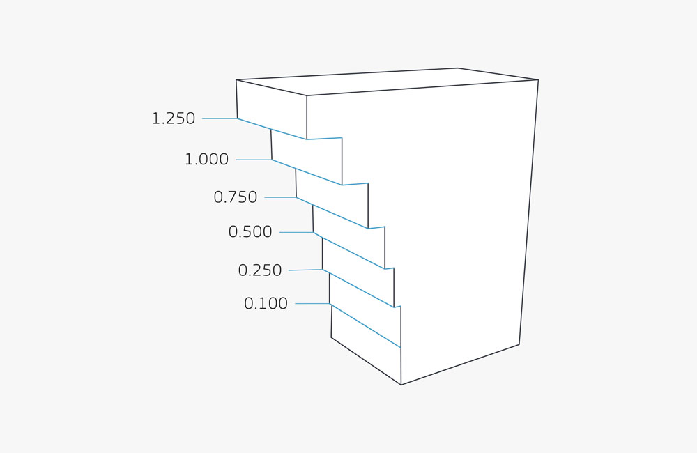
When designing for DMLS, be cautious about overhangs—abrupt changes in a part’s geometry. As seen in this example, if the next layer is larger than the previous layer, it will create an overhang. DMLS is fairly limited in its support of overhangs.
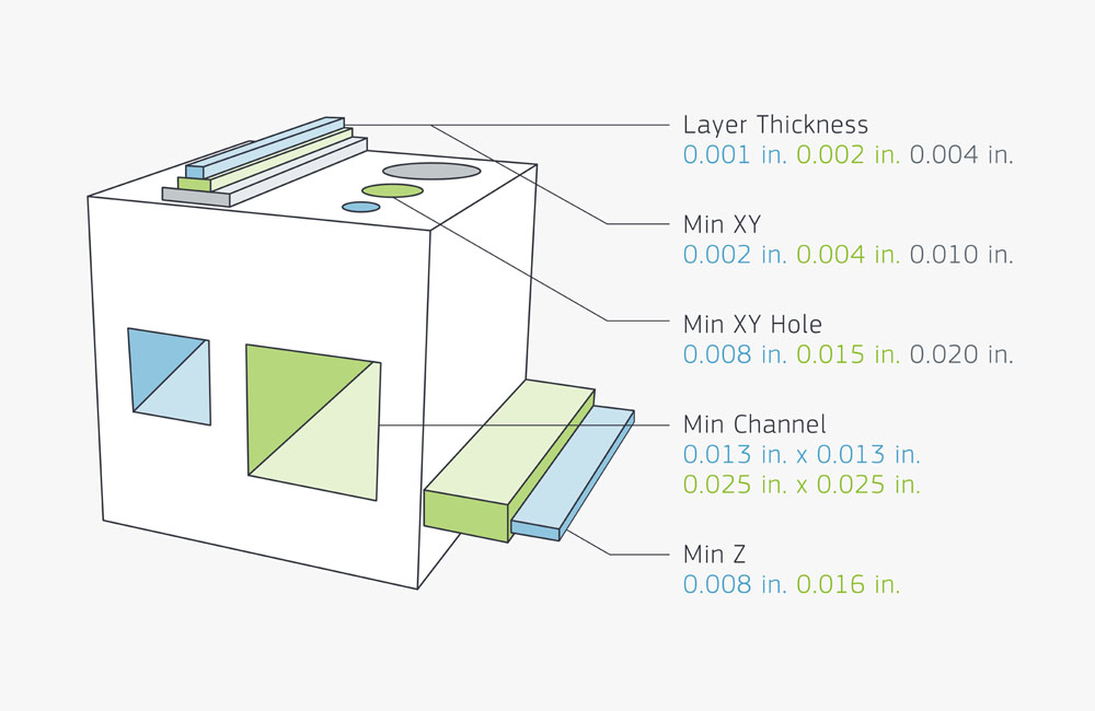
In this illustration, the blue color represents micro resolution (MR), green is high resolution (HR), and gray is normal resolution (NR). Also, the minimum channel and minimum Z dimensions apply to both NR and HR.
Post-Processing for 3D Printing
Looking to boost the strength, clarity, or appearance of your 3D-printed parts? Choose from microfluidic and micro-resolution materials, metal plating, secondary machining, and custom finishes like painting, clear coating, and decaling.
Surface Finish Options
| Unfinished | Dots, or standing "nibs," remain evident on the bottom of the part from the support structure remnants. |
| Natural | Supported surfaces are sanded down to eliminate the support nibs. |
| Standard | Supported surfaces are sanded, and the entire part is finely blasted for a consistent look. Note that the layers are still present. |
| Custom | Soft-touch paint, clear part finishing, painting, masking, color matching, decals/graphic, and texture finishes are available. |

An unfinished ABS-like part that was 3D-printed with SLA.
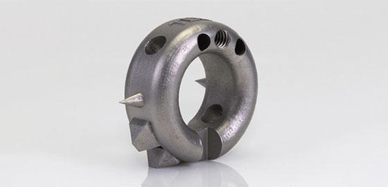
A metal part with standard finish that was 3D-printed with DMLS.
Custom Finish Options
| Clear Coat | Clear cosmetic finish that can be applied to ABS-like Translucent/Clear (WaterShed XC 11122) and PC-like Translucent/Clear (Accura 60) materials. |
| Painting | After smoothing the part with sanding and polishing, parts can be painted with automotive-grade paint. Provide a pantone color with your quote request. We also offer soft-touch painting. |
| Plating | Electroless nickel plating can be used to achieve parts that are similar to cast aluminum or magnesium. |
| Dyeing | Dyeing is another method for adding color to 3D prints. This is faster option with a limited color selection, so is a more cost-effective choice than painting. |
| Decaling | Decaling can be used to add a logo or other graphics to boost cosmetics or function. |
| Polishing | We can polish parts to a mirror-like finish. If this is a requirement, we ask that you provide either a drawing or image that indicates your finish expectations. |
| Heat Treatment | Harden and strengthen metal 3D prints with multiple heat treatment options: NADCAP heat treatment, hot isostatic pressing (HIP), solution annealing, and aging. |
| Machining | Machine metal 3D prints to achieve exceptional surface finish quality or meet tight tolerances. |
| Vapor Smoothing | Used on select nylon parts made using the SLS or MJF printing processes. A chemical vapor significantly reduces surface roughness. |
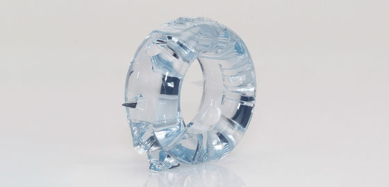
An ABS-like part with custom clear coat that was 3D-printed with SLA.
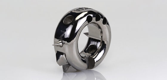
A metal part with high polish that was 3D-printed with DMLS.
So, whether you’re looking for prototypes or end-use production parts, additive manufacturing has a lot going for it. From geometric flexibility in a variety of materials to rapid iteration that gets you high-quality parts within just days, our various 3D printing processes provide you with what you need to get the job done. If you have any questions regarding your quote or design, talk with our applications engineers to help guide you through the process. We look forward to working with you on your next project!
3D Printing Resources
Where to Get 3D Printing Files
There’s a thriving market for free 3DP CAD files. Here are just some of the places people look to find something they might be able to work with:
Software for 3D Printing Design
There are quite a few options available to you when it comes to choosing a computer-aided design (CAD) program or additional support software. Here are just a few:
- 3DXpert
- Altair Inspire Print3D & OptiStruct
- Ansys Additive Suite
- Autodesk Fusion 360
- CREO
- Materialise
- MSC Apex Generative Design
- nTopology
- Siemens Solid Edge
- SOLIDWORKS
There are even some powerful free CAD programs you can try if you’re just starting out.
Accepted CAD Files for 3D Printing
No matter what program you choose to work with, note that we accept CAD in the following file formats:
- MESH (.stl)
- STEP (.stp/step)
- SOLIDWORKS (.sldprt)
- IGES (.igs/.iges)


