Design Guidelines for Sheet Metal Fabrication
These guidelines for sheet metal fabrication include important design considerations to help improve part manufacturability, enhance cosmetic appearance, and reduce overall production time.
Minimum Dimensions
| Flat Part |
0.250 in. x 0.250 in. 6.35mm x 6.35mm |
|---|---|
| Formed Part |
0.500 in. x 0.500 in. 12.7mm x 12.7mm |
Maximum Dimensions
| Size |
39 in. x 47 in. 990.6mm x 1,193.8mm |
|---|---|
| Bend Length |
47 in. 1,193.8mm |
Tolerances on One Surface
| Feature | Material < .13 in. | Material > .13 in. |
|---|---|---|
| Edge to Edge | 0.005 in. (0.13mm) | 0.015 in. (0.38mm) |
| Edge to Hole | 0.005 in. (0.13mm) | 0.015 in. (0.38mm) |
| Hole to Hole | 0.005 in. (0.13mm) | 0.015 in. (0.38mm) |
| Bend to Hole | 0.015 in. (0.38mm) | 0.025 in. (0.635mm) |
| Bend to Edge | 0.010 in. (0.25mm) | 0.020 in. (0.508mm) |
| Bend to Bend | 0.015 in. (0.38mm) | 0.025 in. (0.635mm) |
Tolerances on Multiple Surfaces
(across bends)
| Feature | Material < .13 in. | Material > .13 in. |
|---|---|---|
| Edge or Hole to Formed Feature | 0.010 in. (0.25mm) | 0.020 in. (0.508mm) |
| Measurements Across 2 Bends | 0.015 in. (0.38mm) | 0.025 in. (0.635mm) |
| Measurements Across 3+ Bends | 0.030 in. (0.76mm) | 0.040 in. (1.016mm) |
Sheet Metal Material Thickness Range
Because sheet metal parts are manufactured from a single sheet of metal, the part must maintain uniform wall thickness. Sheet metal thickness ranges from 0.024 in. (0.609mm) to 0.250 in. (6.35mm). Use the tables below to see what thicknesses are available for each of our six material types: Aluminum, Brass, Copper, Stainless Steel, Steel: CR Non-treated, Steel: CR Galvanneal or CR Galvanized.
Sheet metal thickness ranges from 0.024 in. (0.609mm) to 0.250 in. (6.35mm)
| Steel | Stainless | Aluminum | Copper | Brass | ||||||
|---|---|---|---|---|---|---|---|---|---|---|
| CRS/HRPO* | Galvanneal | Galvanized | 304-2B | 304-#4 | 316-2B | 5052-H32 | 6061-T6 | C101 | C110 | C260 |
| 0.024 | 0.028 | 0.028 | 0.024 | 0.024 | 0.024 | 0.025 | 0.025 | 0.025 | 0.025 | |
| 0.030 | 0.034 | 0.034 | 0.029 | 0.029 | 0.029 | 0.032 | 0.032 | 0.032 | 0.032 | 0.032 |
| 0.036 | 0.040 | 0.040 | 0.036 | 0.036 | 0.036 | |||||
| 0.042 | 0.040 | 0.040 | 0.040 | 0.040 | 0.040 | |||||
| 0.048 | 0.052 | 0.052 | 0.048 | 0.048 | 0.048 | 0.050 | 0.050 | 0.050 | 0.050 | 0.050 |
| 0.060 | 0.063 | 0.063 | 0.060 | 0.060 | 0.060 | 0.063 | 0.063 | 0.064 | 0.062 | 0.063 |
| 0.075 | 0.079 | 0.079 | 0.075 | 0.075 | 0.075 | 0.080 | 0.080 | 0.080 | 0.080 | 0.080 |
| 0.090 | 0.093 | 0.093 | 0.090 | 0.090 | 0.090 | 0.090 | 0.090 | 0.093 | 0.093 | 0.093 |
| 0.105 | 0.108 | 0.108 | 0.105 | 0.105 | 0.105 | 0.100 | 0.100 | |||
| 0.120 | 0.123 | 0.123 | 0.120 | 0.120 | 0.120 | 0.125 | 0.125 | 0.125 | 0.125 | 0.125 |
| 0.135* | 0.138 | 0.138 | 0.135 | 0.134 | 0.135 | |||||
| 0.164* | 0.165 | 0.160 | 0.160 | |||||||
| 0.179* | 0.187 | 0.190 | 0.190 | |||||||
| 0.239* | 0.250 | 0.250 | 0.250 | |||||||
*These thicknesses are available as Hot Rolled, Pickled & Oiled (HRPO) only

Finishing Options for Sheet Metal Components
We offer welded assemblies, standard mill, edge breaking, and orbital-sanded surface finishes along with a number of additional sheet metal finishing options:
- Seam, tack, and stitch welding
- Hardware insertion and riveting: Standard PEM sheet metal hardware
- Powder coating: A variety of powder coat paint colors available in textured and non-textured finish, including RAL colors.
- Silk screening: Colors mixed to closely match most Pantone numbers
- Assemblies: POP-riveted and welded
- Plating: Anodize, chromate, zinc, and passivate

Sheet Metal Surface Finish Guide
Check out our sheet metal guide for a quick snapshot of our Standard and Cosmetic finishing options available for various sheet metal materials.
Download GuideBending Design Guidelines for Sheet Metal Fabrication
We’ve designed these guidelines to help product designers enhance their knowledge of sheet metal fabrication processes and recognize the key factors that influence part quality and consistency. Leveraging this guidance on your next project can help you manage costs, achieve your desired aesthetic, and ensure consistently accurate parts.
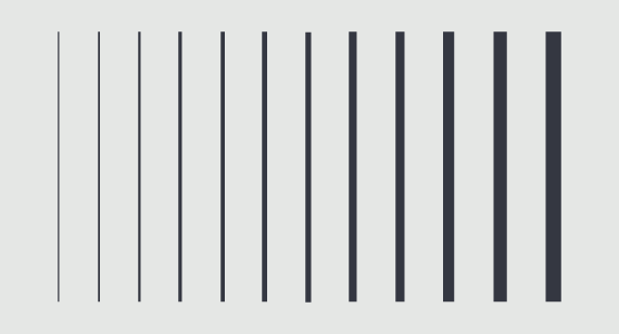
Understanding Brake Lines
Brake lines occur as a result of the force applied on the sheet metal during the bending process, which takes place in a press brake. They are a natural consequence of the manufacturing process, and without additional treatment or processing, will be present on your final product.


For products that are cosmetic in nature or require specific aesthetic qualities, removing brake lines is possible through secondary processing such as:
- Using a direct oscillating (DA) tool to blend the brake line into the surrounding material
- Placing a rubber slip sheet atop the die tooling during bending
- Applying a finish—such as powder coating—after forming that covers the full surface of the part. Note: Plating thickness is often insufficient to cover brake lines. Therefore, brake lines will be visible after plating is applied
- If a uniform finish (without visible brake lines) is needed for your part application, contact our applications engineers to discuss which method will best suit your needs.
Feature Proximity to Bends
There is a fundamental rule that when sheet metal is bent in a press brake, the material stretches along and in the proximity of a bend line. Any feature that is within proximity of a bend (typically within 4x material thickness of the bend) is at risk for deformation.
Fortunately, there are several ways to account for this and achieve the intended design objective. Here are the common design solutions for this situation:

| Possible Solutions | Rationale for Using this Solution |
|---|---|
| Allow the feature to deform during bending |
|
| Re-locate/move the at-risk feature |
|
| Change the bend radius |
|
In most cases, these solutions do not affect cost and lead time associated with your design, but they can help you avoid additional processing costs across the lifespan of your part.
Unsure which solution works best for your design? Our sheet metal experts are standing by to provide a free 30-minute design review (same day appointments available). Schedule your design review here.

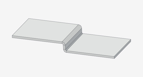
Extending Features Through Bends
There is one additional option you can consider to avoid deformation along bends—extending a feature through the bend.
In images A and B (below), the bracket includes two L-shaped cutouts that end along the bend. The material is deformed at the point where the top of each L meets the bend.


Following the feature distance guidelines in the placing features near bends section of our sheet metal DFM toolkit, eliminating deformation is possible by extending the L-shape through the bend line. This approach removes material where the bend typically would be located and is shown in images C and D below.


Fabricating Designs with Features Along a Bend
Of course, there can be design scenarios in which feature location is crucial to your product requirements. In these situations, modifying a feature to relieve material along a bend or moving a feature away from a bend may not be possible.
Designs that fall into this category often can be fabricated to achieve dimensional accuracy, but this comes with additional cost and lead time. Instead of accounting for how to design around the physical limitations of bending, features can be incorporated after the bending process. Hand drilling holes, and CNC milling of cutouts and pockets after bending an alternative to laser-cutting features before bending.
NOTE: Drilling and CNC machining are additional services which as cost and lead time to a product. Depending on which manufacturing technology you plan to use for production volumes, these costs may have a lasting impact on the total cost of your project.
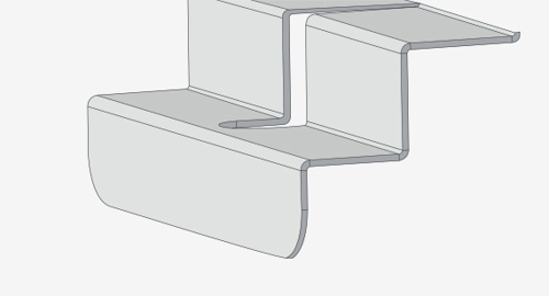
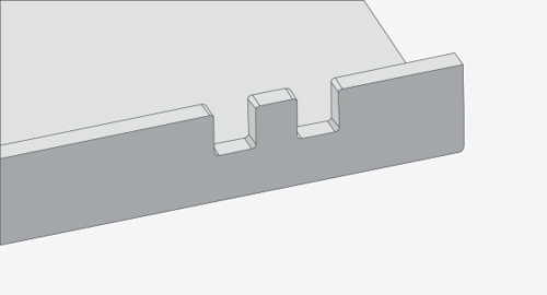
Minimum Flange Lengths
To accurately achieve a bend in a press brake, a design must make three (3) points of contact with the machine. The image to the right illustrates these points of contact.
If a design makes only two points of contact, you could end up with a deformed flange on your final part. In the image below, the center portion of the "H" bracket has two flanges on the z-axis. These flanges did not make three points of contact in the press brake, resulting in inconsistent and deformed bends.


You can avoid quality-related fallout from this issue by following the guidance provided in our design for manufacturability toolkit. Using this link will take you directly to the solution for overcoming minimum flange lengths in your design. If your design requires flanges to meet your original dimensions, we recommend contacting our applications engineers at 877-479-3680 to discuss alternate fabrication methods such as post-forming machining.
Hardware Inserts near Bends
Including hardware inserts in your sheet metal design is a versatile and cost-effective way to join components together. Depending on your design requirements, you may find yourself placing hardware holes and inserts near to bends.
In situations where hardware inserts are close to bend lines, it is important to consider that any hardware hole deformation (due to material stretching in the press brake) may affect the functionality of the insert itself.
If you have flexibility in where you place your hardware inserts on your design, we recommend reviewing our feature proximity to bends guidelines earlier in this document. Following this advice will ensure consistent part quality and hardware functionality.
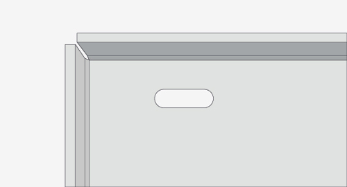
The Challenge with Hardware Holes and Inserts near Bends
If hardware location is paramount to your requirements, the mounting bracket below illustrates how the bending process influences hardware installation and functionality. Read on for a recommendation to overcome the challenge.
If hardware location is paramount to your requirements, the mounting bracket below illustrates how the bending process influences hardware installation and functionality. Read on for a recommendation to overcome the challenge.


Solving the Challenge with Material Relief
You may be familiar with the sheet metal manufacturability term relief, most used in the phrase bend relief, but it can be applied to other design scenarios. The act of relieving sheet metal includes strategically placing cut-outs to allow for material stretching during bending without distorting critical features.


For hardware holes close to bends, adding cutouts around the hardware hole provides the necessary material relief during bending and leaves the hole undistorted. This approach has the benefit of maintaining design intent and keeping part costs low.
To ensure your inserts are seated correctly into the material, it is important to know how much material is required around the hole. The online PennEngineering® (PEM) product catalog is a helpful tool.
When investigating a specific product in the PEM catalog, under the "specifications" section, refer to "min. distance hole C/L to edge." This number (displayed in millimeters) is the minimum distance required from the hole's centerline to the edge of the design. For example, check out this sample product page for CLS-M4-2.
Considering material relief during the design phase of your sheet metal project has benefits beyond hardware installation, including:
- Preventing material tears and cracks along bend lines or stress points such as corners
- Minimizing quality issues such as warping or feature deformation that could affect dimensional accuracy
- Enabling consistency of production form part-to-part and order-to-order
- Improving part durability and performance by reducing material stress
- Aiding assembly and fit by avoiding interference issues where parts or components meet
Design Guidelines for Common Sheet Metal Features
We hold a +/- 1 degree tolerance on all bend angles. We offer a wide range of common bend radii, but our standard options are .030 (.762mm), .060 (1.524mm), .090 (2.286mm), .120 (3.048mm). These four bend radii tooling choices are available in a 3 day lead time. Minimum flange length on sheet metal parts must be at least 4 times the material thickness.
It is recommended to use the same radii across all bends, and flange length must be at least 4 times the material thickness.
We form both open and closed hems. The tolerance of a hem is dependent upon the hem's radius, material thickness, and features near the hem.
We recommend that the minimum inside diameter equals the material thickness, and a hem return length of 6x material thickness.
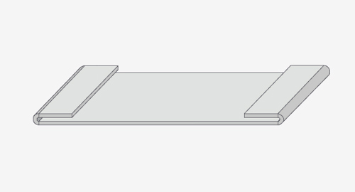
Offsets are used to create Z-shaped profiles in sheet metal parts. We offset height tolerance at +/-0.012 in. (0.304mm) from top of sheet to top of form and recommend an offset of 0.030 in. (0.762mm).
Additional standard options include: available 0.060 in. (1.524mm), 0.093 in. (2.362mm), 0.125 in. (3.175mm), 0.187 in. (4.749mm), 0.213 in. (5.410mm), 0.250 in. (6.35mm), 0.281 in. (7.137mm), and 0.312 in. (7.924mm).
Holes and slots should be a minimum of material thickness in diameter. If a material is 0.036 in. (0.914mm) or thinner, the hole should be 0.062 in. (1.574mm) from the material edge; if the material is thicker than 0.036 in. (0.914mm), the hole should be at least 0.125 in. (3.175mm) from the material edge to avoid distortion. If hardware inserts are required, the spacing should be according to manufacturer’s specifications.
Notches must be at least the material’s thickness or 0.04 in. (1.016mm), whichever is greater, and can be no longer than 5 times its width. Tabs must be at least 2 times the material’s thickness or 0.126 in. (3.200mm), whichever is greater, and can be no longer than 5 times its width.
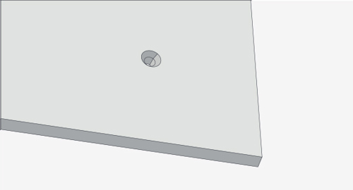
We offer both machined and formed countersinks—conical holes cut into a manufactured object allowing a screw, nail, or bolt to be inserted flush with the surface.
We recommend the major diameters of countersinks measure between 0.090 in. (2.286mm) and 0.500 in. (12.7mm) using one of the following standard angles: 82°, 90°, 100°, and 120°.
Tolerance for formed countersink major and minor diameters is +0.020/-0.010 (+0.508mm/-0.254mm).